| Render Output |
Sets the type of output for the rendering.
- Color and Alpha — Color output with alpha channel for background (24 bit color + 8 bit alpha), also referred to as RGBA. This is a 32 bit image. After the rendering is completed, you add any image or color for background, provided the environment is not "visible to camera."
- Ambient Occlusion — Shades the model in such a way as to accentuate its nooks and crannies. Ambient Occlusion means what areas of your model are hidden from ambient light in the scene. In other words, which portions of your model are shadowed. Ambient Occlusion is also a predefined render setup. You can get the ambient occlusion render setup by clicking the down arrow on the Render Setup Manager icon and selecting Ambient Occlusion from the drop-down menu. Then clicking Render icon in the Luxology Render dialog, renders the model with the Ambient Occlusion render output. Setting the Output to Ambient Occlusion is equivalent to using all white diffuse surfaces lit by a white environment. For example, if half the rays coming from the point being shaded hit geometry, then the point is half occluded and will be 50% grey. If all the rays hit geometry, then the point will be black. If no rays hit the geometry, then the point will be 100% white. The resulting baked map then can be used as a diffuse texture layer with the blend mode set to multiply. This is a very common technique used in film production to optimize certain elements in a shot so that full global illumination solving is not required on a frame by frame basis. This is a very good technique also for quickly dirtying up your model as it tends to darken areas that would generally collect dust and dirt in the real world. Ambient Occlusion uses Global Illumination to perform the rendering. The quality of the Ambient Occlusion pass is dependent on the number of Occlusion Rays used. The default value of 64 may result in grainy images. You can improve quality, (at the expense of render time) by increasing the number of Occlusion Rays to 256 or more.
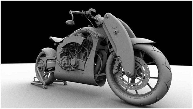
Example of ambient occlusion
- Depth — Produces grayscale images where the values are based on the distance from the back-clipping plane or, if one is not defined, the back of the geometry visible in the scene. Lighting has no effect when using Depth output. This option can be used, for example, to create a displacement map from existing geometry. Where required, you can use a selection set to include multiple elements in the displacement map. The depth output image also can be used with 3rd party image editors to quickly produce high quality Depth of Field effects by using lens blurring filters. By default, a Top view is used for the image. Where an Auxiliary Coordinate System (ACS) is active and ACS Plane lock is on, the Top view for the ACS is used. If ACS Plane lock is off, then the standard Top view is used.
- Shadow Density — The Shadow Density rendering output renders a channel generated from the density of all direct light shadows in Luxology, exclusive of color shading or texture. The darkest areas of shadow render as white ramping toward black for the areas that would be fully illuminated. When rendering in layers, it is very useful to have shadows rendered separately giving one control of color and transparency. You could easily invert this channel in an image editing application and layer it over the unshadowed render set to multiply, giving control over how dark the shadows are based on the layers transparency.
- Color Only — Output is rendered with the defined colors and materials. This is a color output only and does not have an alpha channel (24 bit color).
- Alpha — Output is rendered with alpha channel only (8 bit grayscale).
- Reflection Shading — The Reflection Shading output generates a channel of all the reflections calculated within a scene, independent of all other attributes.
- Specular Shading — The Specular Shading output generates a channel of all the specular shadings within a scene, independent of all other attributes.
- Subsurface Shading — The Subsurface Shading output generates a channel of all the subsurface scattering shadings within a scene, independent of all other attributes.
- Transparent Shading — The Transparent Shading output generates a channel of all the transparent shadings within a scene, independent of all other attributes.
- Illumination Total — The Illumination Total output generates a channel of the full illumination in a scene, including shadows cast by direct sources, independent of all other surfacing attributes.
- Illumination Indirect — The Illumination Indirect output generates a channel exclusive to the illumination in a scene from all indirect sources such as image based lighting and luminous polygons, independent of all other surfacing attributes.
- Illumination Direct — The Illumination Direct output generates a channel exclusive to the illumination in a scene from all direct light items such as distant lights, area lights, point lights and spot lights, independent of all other surfacing attributes.
|
| Shadows |
If enabled, shadows are included in render. The sharpness of the shadows’ edges can be set from the list box at the right. Where softer shadows are required, more samples are taken.
- Per Light — Shadow type is that as defined by each light.
- Sharp — 1 sample.
- Soft-Coarse — 16 samples.
- Soft-Medium — 64 samples.
- Soft-Fine — 160 samples.
- Soft-Very Fine — 256 samples.
|
| Reflections |
If enabled, reflections are rendered. |
| Reflection Depth |
(Reflection enabled only) Sets the number of reflection bounces that are rendered (allowed values - 0 to 999). |
| Transparency |
If enabled transparency is rendered. |
| Refraction Depth |
(Transparency enabled only) Sets the number of transparent surfaces a ray can travel before no longer being considered (allowed values - 0 to 999). |
| Stereo |
When on, two images are rendered and displayed as a side-by-side, cross-eyed stereo pair. The cross-eyed stereo is viewed by crossing your eyes until you see a stereo image appear between the two images. This method is referred to as free view because you do not need stereo glasses to see the stereo image. The Stereo Image Type setting on the Luxology Render dialog also allows you to switch between displaying a side-by-side stereo pair or an anaglyph display. The setting is only available if Stereo is on in the Render Setup Manager dialog.
|
| Ray Threshold (%) |
Sets, as a percentage, the minimum contribution that a reflected or transmitted ray needs before that ray will be computed. |
| Depth of Field |
(Antialiasing enabled, in a camera view, only) If enabled, Depth of Field effects are rendered. When Depth of Field is enabled, the f-Stop field is enabled also. In this field, you can key in, or select from a drop-down menu, the f-Stop for the camera lens (lens aperture) to simulate the depth of field of a camera.
Depth of field refers to the range of distances that an image is in focus for a given lens aperture. Objects beyond that range typically will appear somewhat out of focus — the further outside the range, the more out of focus. When an image is rendered with Luxology and the Depth of Field check box is on, changes in focus will be rendered.
Associated with this setting is the Focal Distance setting for the Camera Position settings in the Define Camera tool.
Note: For best results use a high antialias sampling rate (256 -1024).
|
| Camera Projection |
Allows you to select the type of camera projection. Options are:
- From View - Sets the projection mode from the view selected for performing the render. The projection mode in this case will be either Perspective or Orthographic.
- Spherical - Renders (equirectangular) spherical images that can be viewed as a panorama using FSPViewer or to save the resulting render as an image file (.HDR or .EXR) and used as a HDRI (high dynamic range imaging) environment.
- Cylindrical - Captures the entire view from the perspective of a tube, removing the polar areas of the projection.
- Spherical VR and Cylindrical VR - Used for virtual reality applications such as a Google Cardboard and Samsung Gear.
|
| Ignore Default Lighting |
If on, ignores the view’s lighting when the view has default lighting applied. |
| Ignore Open Elements and Text |
If on, restricts rendering processes to only those elements that include an area component: surfaces and all closed elements such as shapes, ellipses, and complex shapes. Conversely, all open elements, such as lines, arcs, text, and points, are not rendered (and therefore not displayed in rendered images). |
| Render Geometry Outside View |
If on, the complete scene is used to compute the rendering solution, including geometry behind the camera. |
| Render Visible Edges |
If on, a visible edges overlay file is created that can be overlaid on top of any matched Render Output. |
| Render Visible Edges Settings |
Click the icon to display options for changing the visible edges options. Controls on the General tab are identical to controls on the Hidden Line Settings dialog General tab. Controls on the Symbology tab are identical to those on the Export Visible Edges dialog Symbology tab. |
| Contour Shading |
If on, contours are added to the image in post-processing (after rendering finishes). Contours are added only to the surface boundaries and not every edge. With contours, you can have the effect fade with distance. The contour options need to be set prior to rendering.

Left: Contour Shading on; right: Contour Shading off
|
| Contour Shading Settings |
Click the icon to display options for changing the contour color and width, to turn on fade with distance and for changing the Crease Threshold. Crease Threshold is used for rendering contours with luxology. When the angle between triangles in a mesh is lower than the angle specified, then a line is drawn along that boundary.
|
| Texture Filtering Override |
Allows you to override the texture filtering for all texture maps in the file. |
| Texture Antialiasing Override |
Allows you to override the texture antialiasing for all texture maps in the file. |
| Stroke Tolerance |
Controls the number of triangles that curved surfaces are broken into before being rendered. Smaller values produce smoother results but at the expense of render times. Stroke Tolerance can be set in pixels or physical units. |
| Antialias Quality |
Controls the antialiasing quality by setting the number of samples that are taken during antialiasing. You can select a predefined setting, or you can create a custom setting.
The predefined quality options are presented in a list box and they change the number of samples used by Luxology for antialiasing.
- None — 1 sample.
- Low — 4 samples.
- Medium — 8 samples.
- High — 16 samples.
- Very High — 64 samples.
- Custom — User defined (1–1024 samples).
Note: For rendering Depth of Field effects it is recommended that you use between 256 and 1024 samples.
|
| Antialias Filter |
Option menu that lets you set the type of antialiasing filtering. The antialiasing filter determines the pattern to use when evaluating a pixel. For instance, Arch-visual renders tend to look better when the box or triangle filters are selected. They look sharper and crisper than their gaussian counterpart in areas where antialiasing is needed, at either geometric or material borders.
- Box — Each pixel is affected only by the samples within its borders, and each sample is weighted equally. This is sharp but rather artificial. For example, imagine two pixels side by side, and a sample very close to the border between them. That sample will contribute 100% of its color to whichever pixel it lies in (even if it's only inside that pixel by a tiny margin) and 0% to the other pixel.
- Triangle — Each pixel is affected by all the samples within it and also samples up to halfway across all the neighboring pixels. Samples are weighted with a linear falloff based on their distances from the center of the pixel. Sometimes, this is called a Tent or Bartlett filter and is equivalent to the "enhanced antialiasing" added to LightWave in 1996 for use in Titanic. In this case, a sample in the middle of the border between two pixels would contribute roughly equally to both pixels.
- Gaussian — (The default) Performs a more accurate sample. This generally yields the best results although it may be slightly slower than the Box or Triangle options. Each pixel is affected by samples that might be all the way across the neighboring pixels (within a radius of 1.5 pixels of its center), and samples are weighted with a bell curve.
- Catmull-Rom — This filter generally yields slightly sharper results than Gaussian.
- Mitchell-Netravali — This filter offers good results when dealing with problematic moire created by fine texture patterns.
|
| Antialias Samples |
Controls the number of antialias samples per pixel. |
| Antialias key |
Is synchronized with the slide control in the Luxology Render dialog. Lets you quickly adjust keyed values inside the selected render setup. When keyed setting is off, ignores slider adjustment. When keyed setting is on, the slider adjusts value. Delivered render setups have the appropriate key values activated. |
| Occlusion Rays |
(Render Output set to Ambient Occlusion only) Sets the number of indirect rays used (default 64). |
| Occlusion Range |
(Render Output set to Ambient Occlusion only) Sets the distance an indirect ray travels before being terminated. In the case of a ray being terminated due to the indirect range value, it is assumed that the ray would eventually hit the environment background. For more on this topic see Indirect Range in the Global Illumination section. |
| Bloom |
Bloom occurs when a very bright part of an image neighbors a very dark part, and the bright part appears to glow. If on, Bloom simulates this effect by removing excess energy from a pixel and distributes it around to its neighbors. |
| Bloom Radius |
Sets the distance in pixels that energy is distributed, controlling the size of the glow. Increasing this value enlarges the bloom effect. |
| Bloom Threshold |
Sets the lower threshold to which pixels are effected by Bloom. Lower values mean less bright pixels are affected by bloom.
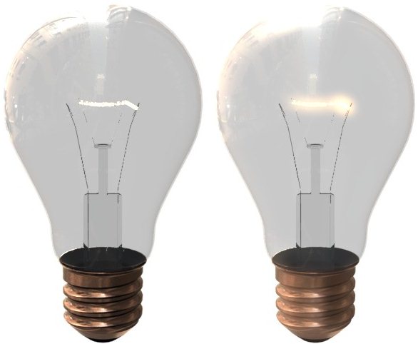
Without bloom on left and with bloom effect on right, you can clearly see the effects of bloom on filament which has a very high glow value applied.
|